

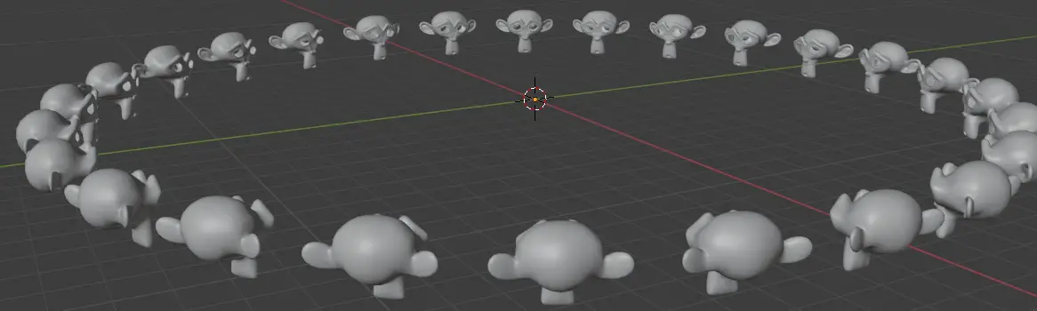
This tutorial is the continuation of the previous tutorial, in the previous tutorial, we were able to make the half of the objects face the center while the other half were off by 180 degree angle. We are going to fix this issue by adding some 180 degrees to half of the instance objects that are not facing the center. Blender version 2.93 is used.
In the previous tutorial, we added a Frame node in Geometry Nodes. And before that made the circular array face the center using Geometry Nodes. This is the continuation of the tutorial series.
We are going to add 180 degrees to the instance objects that are not facing the center.
First of all, we need to determine which of these is not facing the center. Those are the instance objects that have the X value less than 0. We need to compare the values.
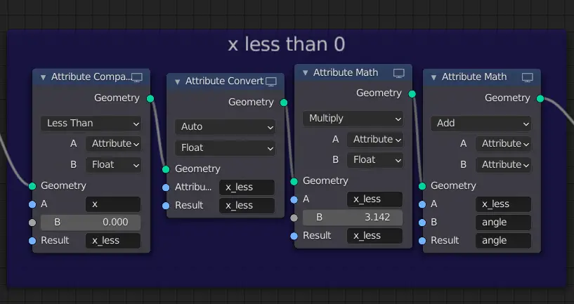
Add Attribute Compare node for x positional value less than 0.
Add an Attribute Compare node by clicking Add > Attribute > Attribute Compare before the Point Rotate node. Choose the condition to be Less Than. A is an Attribute while B is a float. We need to see if the x value is less than 0. So, in A attribute type x ( this will contain the x positional values of all the instance objects) and the value B will be 0.
The Result will stored in a new Custom Attribute called “x_less”.

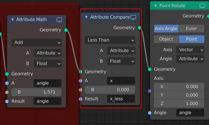
x_less attribute will now have the true or false information on the instance objects. If the instance object has the x positional value less than 0, it will have the value “true” otherwise it is “false”.
But, we need it to be a number. We need to convert it.
Add Attribute Convert node to convert condition to a float number
To convert it, we add Attribute Convert by clicking Add > Attribute > Attribute Convert after the Compare node.
We want the values to convert to numbers, so we select Auto and Float. The value is stored in x_less, so, we enter the Attribute x_less and we get the new values in the same attribute.

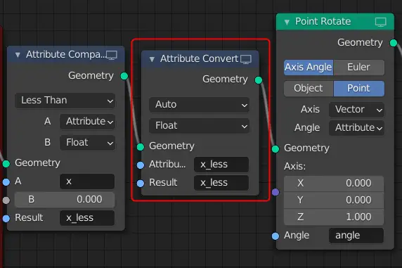
The values are now converted to 0 and 1, such that, the true value is 1 and false is 0. Which means the instance object which has negative x positional value (less than 0) will have the value ‘1’.
Explaining x_less attribute
We will multiply this x_less attribute with 180 degrees and then we will add this value to rotational angle attribute. Remember that, x_less attribute has both 0 and 1 values depending on the instance objects.
| If “x_less” has value 0 | If “x_less” has value 1 |
| When it will be multiplied with 180 degrees, the result will be 0. So, 0 degrees will be added to the instance objects that are already facing the center. | When it will be multiplied with 180 degrees, the result will be 180. So, 180 degrees will be added to the instance objects that are off by a 180 degree angle. That should resolve the issue. |
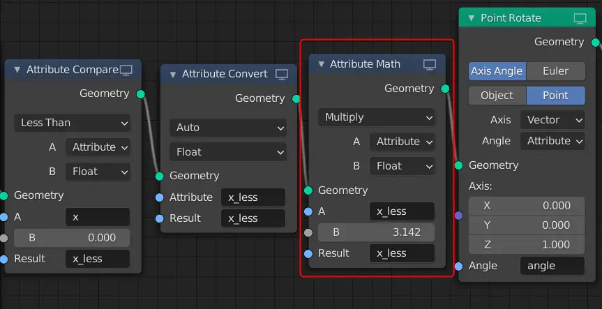
Multiplying half of the instance objects with 180 degrees.
Add a Attribute Math node after Attribute Convert node. Change the operation to Multiply. A should be x_less attribute while B should be a float that is 3.142 radians that is equivalent of 180 degrees. The Result should be stored in the x_less attribute.

We need to add this value to the original angle attribute.
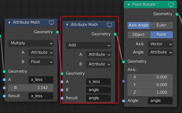
Adding 180 degrees to the angle for half of the instance objects
Add another Attribute Math node, choose the Math operation to Add, A and B should be Attributes. A will x_less and B will be angle attribute. The Result should be angle because we are using angle attribute to rotate the instance objects.

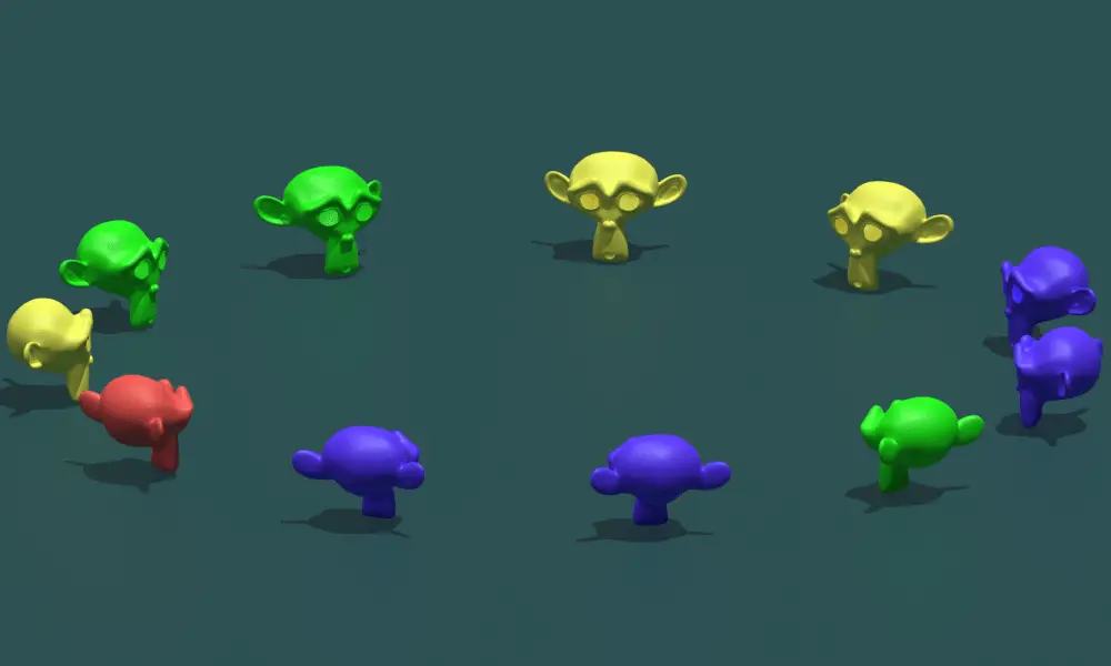
All the instance objects should now be facing the center.

Note that, if all the instances objects are facing away from the center, you may adjust their rotation manually. Make sure the models are facing positive Y axis.
Adding Frame Node
You can combine them in a Frame node by selecting them and pressing CTRL + J.

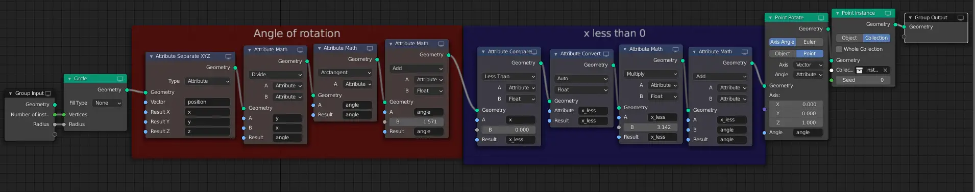
Final Geometry Node Setup
The Final Geometry Nodes setup.
Final Render
The final render image:
Here are more parts of the tutorial series: