

In this tutorial, we are going to use Geometry Nodes to track a target or another object. Blender version 2.93 is used.
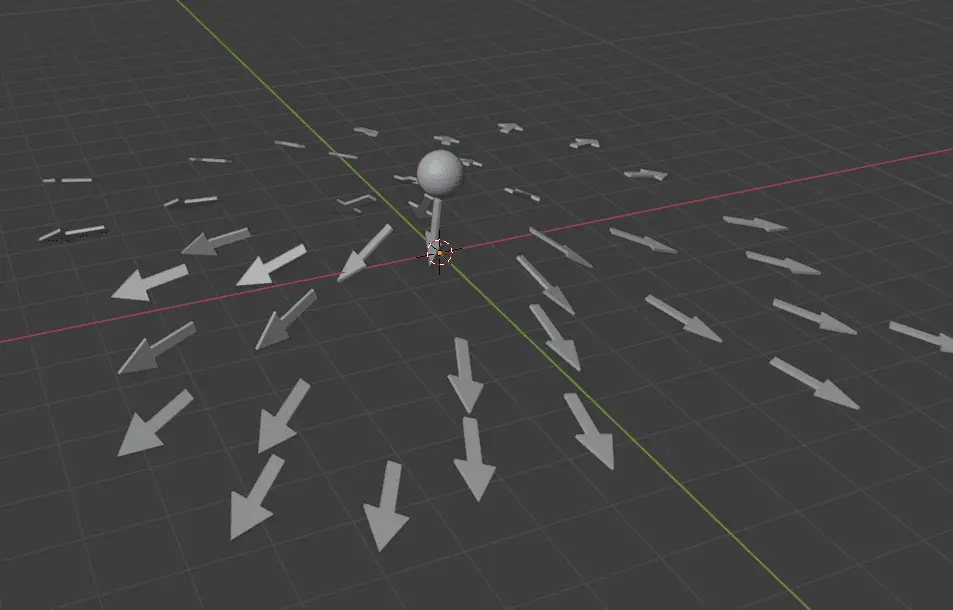
This is how the object tracking will look like:

Setting up Collection for Instances
For this tutorial series, we will use arrows that will track the other object. We will make a separate collection for those arrows named indicators. To make a new collection, press Right Mouse Button in the Outliner, on the right side, and click New Collection.

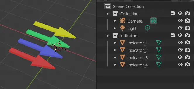
Note that all of the arrows are along the X-axis. Later, this will be important.
It is necessary to apply Rotation and Scale for the objects that we are going to use for the Geometry Nodes, so that the scale and rotation should be as intended.
Select all the objects, press Ctrl+A and click Rotation & Scale.

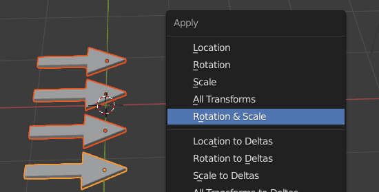
By applying Rotation and Scale, these transform values reset to while keeping the visual object data in space.
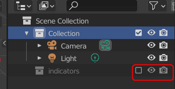
It is recommended to disable the collection which will be used for geometry node. So, that these objects may only be used in Geometry Nodes.

We are going to use point scatter on a plane. All of the objects inside the indicators collection will be instanced on that plane.
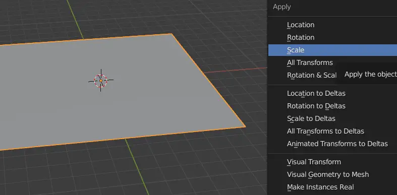
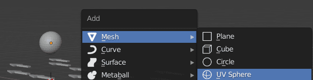
Add a plane by clicking Add > Mesh > Plane. Increase the size of the plane by scaling it.
Apply Scale, so that the size of the objects does not change when they are instanced.

Using Geometry Nodes
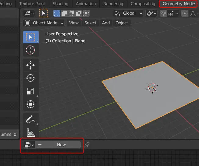
Switch to Geometry Nodes tab from the top ribbon. There are three windows in this tab, 3D Viewport, Spreadsheet and Geometry Node Editor.
We will be using Geometry Node Editor and 3D Viewport for this tutorial.
Select the plane and click New in the Geometry Nodes Editor to add a Geometry Node modifier to that plane.

Add Point Distribute
The Point Distribute nodes scatters the points on a geometry.
To instance the objects, Point Distribute should be used on the plane.
Click Add > Point > Point Distribute to add the point distribute node.

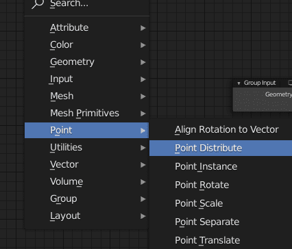
Adjust the new node between Group Input and Group Output.

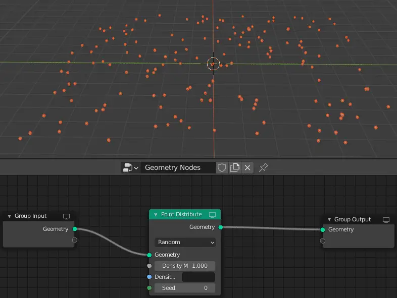
We can see all the points but we need to instance objects in their place.
Add Point Instance
Point Instance node can be used to instance objects at the place of Points or vertices of the geometry.
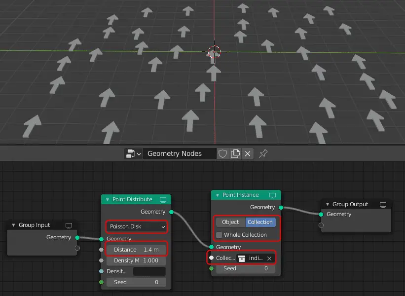
Add a Point Instance node by clicking Add > Point > Point Instance. The node should be added after the Point Distribute node.
In the Point Instance node, change the type to Collection, since our objects are in form of a collection.
Disable the Whole Collection, as we want the objects individually.
In the Collection option, choose the Collection where the objects are.
You might notice that there are many instances on the plane, to add Distance between them, in the Point Distribute node, change the type to Poisson Disk. Increase the Distance parameter.

We have set up the objects which will track the target. Now we will add a target. We will use a sphere as a target.
Adding Sphere as target
Click Add > Mesh > UV Sphere.

Getting Distance between Instances and Target
We need to know the distance between the each arrow and the target(sphere), so we can use it for the angle. This can be calculated using Attribute Vector Math node.
To get the distance between two objects, we can subtract their positional values.
Add Attribute Vector Math
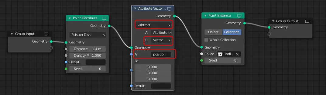
Add an Attribute Vector Math by clicking Add > Attribute > Attribute Vector Math. Place it next to Point Distribute node.
Change the Operation to Subtract, change the B parameter to Vector, because the location of the target will be in Vector form and in the A attribute write position, the position attribute contains position data for all the points and instances.
We have the position data of the arrows, now we need the data of the target (sphere).
Add Object Info
Object Info is the node which contains the information of the object that is selected.
Add the Object Info by clicking Add > Input > Object Info.
In our case, we want the information of the sphere since that is our target. Select the sphere in the Object input, and connect the Location output of the Object Info to the B input of the Attribute Vector Math node.
Type angle in the result.

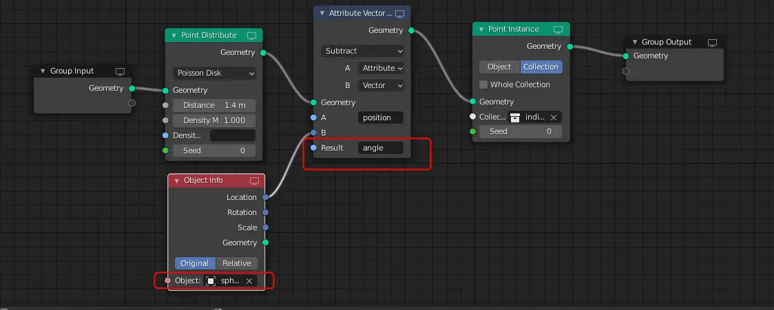
The distance between each of the arrow and the target is now stored in the angle attribute.
We need to rotate the arrows, so that they face the target.
Add Align Rotation to Vector
We will be using Align Rotation to Vector for this purpose. This node uses the Rotation attribute to rotate the points in a specific direction. The Rotation attribute is a built in attribute of the geometry nodes that contains the Rotation data of the points.
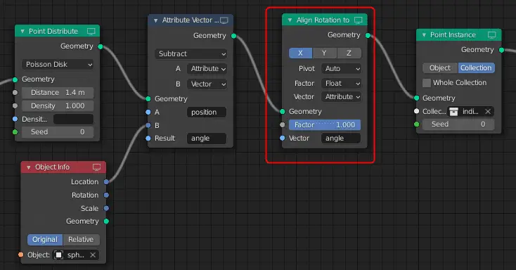
Add Align Rotation to Vector by clicking Add > Point > Align Rotation to Vector. Place it next to Attribute Vector Math.
Since our arrows are facing the X axis, we choose the Axis to be X. The Axis determine the direction which the object faces. You may change according to your requirements.
Change the Vector to Attribute since we have the attribute angle. Type angle in the Vector attribute.

We have used the angle attribute, which is the distance between the target and the arrows to change the orientation of the arrows.
As you can see the all the instances are facing the target with a 180 degree offset.

This can be corrected by changing the orientation of the instances.
This is the Geometry Node Setup, so far .
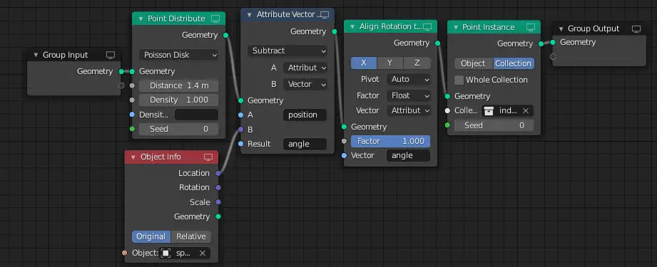
In the next tutorial, we are going to fix the orientation of these instances: Fixing Rotation of Instances of Geometry Nodes.